Super Simple Electrocardiogram ECG Circuit 11 Steps with Pictures Circuit Diagram
BlogSuper Simple Electrocardiogram ECG Circuit 11 Steps with Pictures Circuit Diagram The AD8232 is an integrated signal conditioning block for ECG and other biopotential measurement applications. It is designed to extract, amplify, and filter small biopotential signals in the presence of noisy conditions, such as those created by motion or remote electrode placement.. The AD8232 module breaks out nine connections from the IC that you can solder pins, wires, or other connectors to. Various ECG sensors and modules are available to measure ECG with microcontrollers such as Arduino. These sensors may include electrodes and signal processing circuitry and can be used to read and process electrocardiogram (ECG) data. Here are some examples of popular ECG sensors and modules: 1. The device with which the electrocardiogram is obtained is called an electrocardiograph. Also Read: Build Digital Thermometer using LM35 and Arduino. Features of AD8232 ECG sensor and its working principle. The AD8232 module allows recording the electrical activity of the heart, by obtaining an electrocardiogram or ECG.
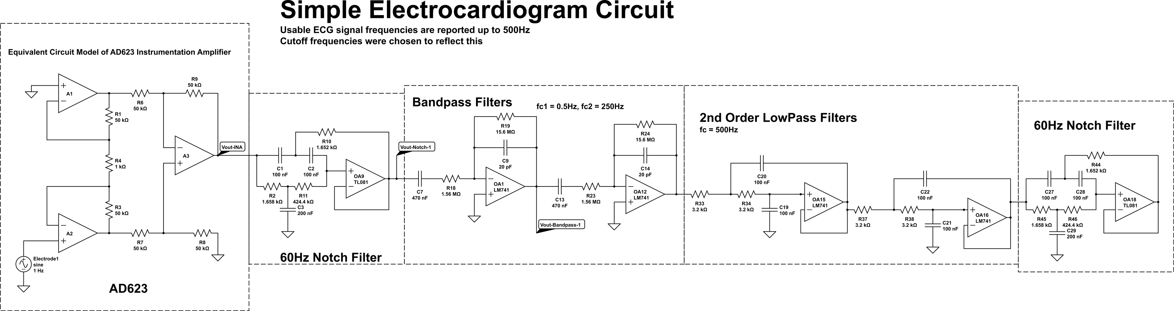
The plot of these voltages over time is called an electrocardiogram (ECG for short). ECGs are typically used to diagnose various forms of heart failure, or passively monitor patient stress. A healthy ECG has specific features that are universal between humans. (This includes a P-wave, Q-wave, R-wave, S-wave, T-wave, and a QRS complex.) ∙ Interface, program and control a microcontroller board (Arduino) with your computer. ∙ Monitor, acquire, store and analyze a digitized single lead EKG signal using the Arduino board and directly using MATLAB. Iskandar WJ, Roihan I, Koestoer RA. Prototype low-cost portable electrocardiogram (ECG) based on Arduino-Uno with Bluetooth
ECG Monitoring system using AD8232 with Arduino or ESP32 IOT Based Circuit Diagram
The serial plotter will allow you to observe the ECG signal, with the peaks and troughs of the ECG visible. An example output can be seen below. You can also create an automatic bpm readout in the same Arduino script. You do this by noting the values the highest peak reaches to define an upper and lower threshold. This tutorial will take you through the steps of building a 3-point electrocardiogram using an Arduino. Before you begin, here's a little info about ECGs: An ECG detects your heart's electrical rhythm and graphs them out. This graph is called a tracing and it consists of several waves that recur with each heartbeat, about 60 to 100 times per
This design allows for an ultralow-power analog-to-digital converter (ADC) or an embedded microcontroller to acquire the output signal easily. Medical uses of ECG. An electrocardiogram can be a useful way to find out whether your high blood pressure has caused any damage to your heart or blood vessels.
IoT Based ECG Monitoring with AD8232 ECG Sensor & ESP32 Circuit Diagram
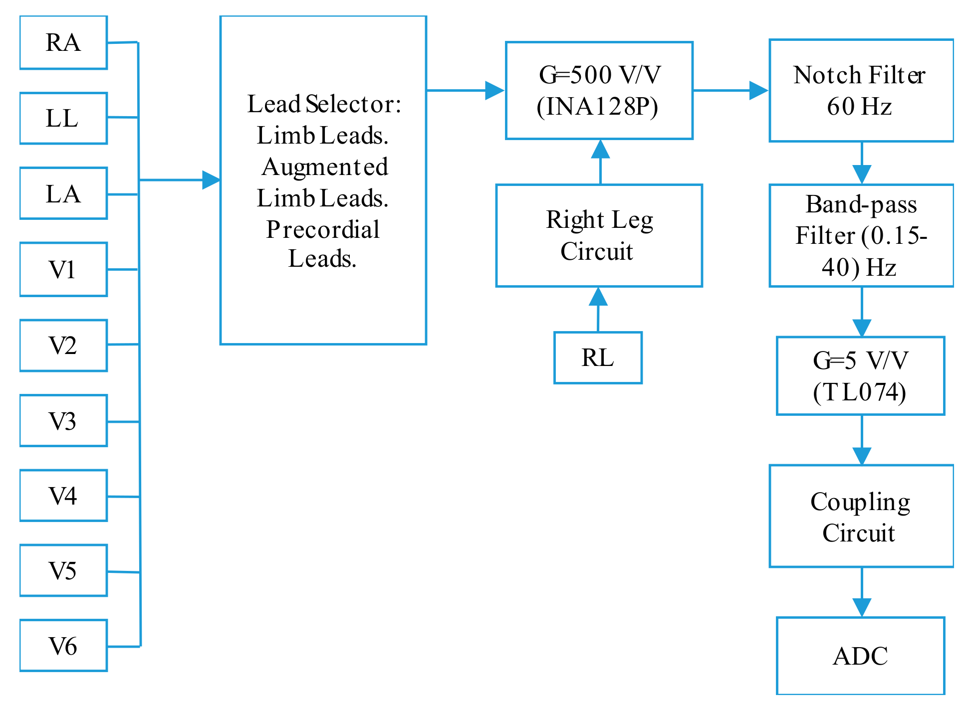
We can brake the device into four main parts parts: Mode Selector, Microcontroller, Two-Stage low pass filter, and the Output voltage-divider.The ecg-simulator-schematic file shows all of the electrical connections and components used to build the simulator and shows which components are used to create each of the four main parts.
