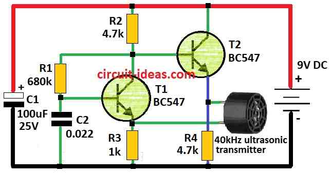
Simple Ultrasonic Security Alarm Circuit Circuit Diagram
BlogSimple Ultrasonic Security Alarm Circuit Circuit Diagram An Ultrasonic Security Alarm Circuit acts like an invisible force field for your home.. It uses high frequency sound waves, like super squeaks that humans cannot hear to detect movement.. Imagine the circuit sending out these sound waves and then listening for them to bounce back. If something walks through the area and disrupts the waves the circuit knows someone might be there and triggers
You can use door/window magnetic sensors, ultrasonic sensors, or even pressure sensors, depending on the specific application you have in mind. 3. Is it safe to build an alarm circuit at home? Creating a simple alarm circuit is an enriching experience that offers both practical benefits and a deeper understanding of circuit design. Whether

Simple Arduino Alarm System : 5 Steps Circuit Diagram
When writing the code we will not to use any libraries. I set the maximum distance to 100 cm for example purposes. However you can choose what ever distance you would like to set as the maximum distance where the buzzer will go off. Just make sure if you are changing one number then just check the rest of the code and make sure the numbers make
Each HC-SR04 module includes an ultrasonic transmitter, a receiver, and a control circuit. There are only 4 pins that you need to know about the HC-SR04 Sensor: VCC (Power), GND (Ground), Trig (Trigger), and Echo (Receive), and. You will find this sensor very simple and easy to set up and use for your next DIY projects & tutorials.

UltraSonic Proximity Alarm : 5 Steps (with Pictures) Circuit Diagram
The figure above shows a simple IC 741 based ultrasonic sound sensor alarm circuit. The detecting device used here is an ordinary electret condenser mic. The mic input is fed to the inverting input of the IC pin#2. How it Works. Pin#3 of the IC is appropriately clamped to a suitably selected reference voltage with respect to the pin#2 of the IC. UltraSonic Proximity Alarm: This is a quick and easy guide on how to make a proximity alarm using a HC-SR04 Ultrasonic sensor, Arduino UNO, Arduino breadboard, and a 6V DC buzzer. Once you have completed the physical circuit, now you plug in the code for the Arduino UNO. Copy and paste the code below.