Minimalistic Led Clock 5 Steps with Pictures Circuit Diagram
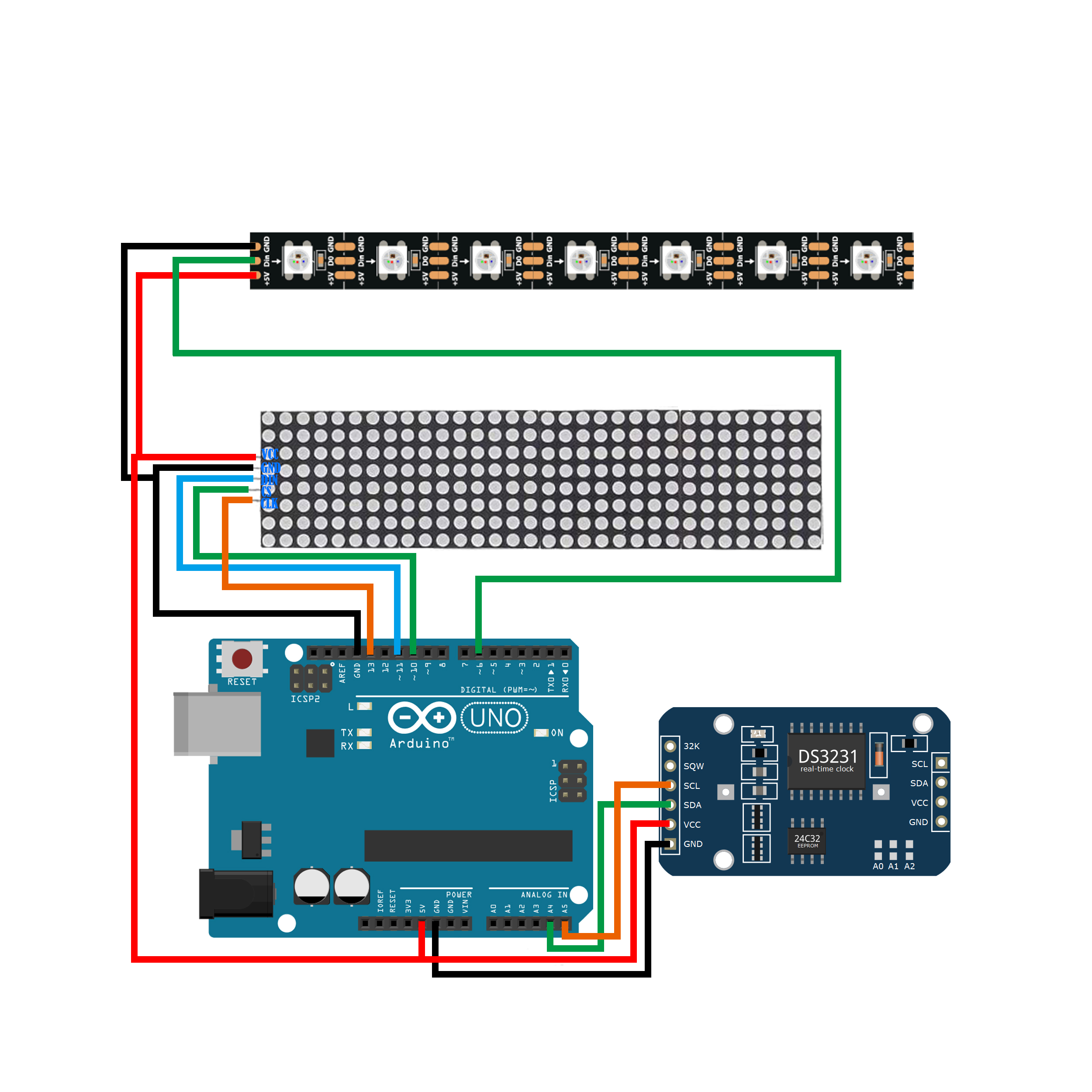
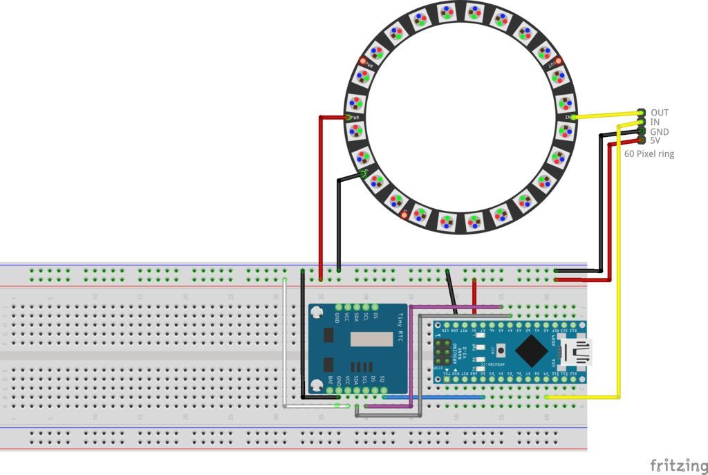
BlogMinimalistic Led Clock 5 Steps with Pictures Circuit Diagram Let's put our LED array to good use and build a binary clock using an Arduino Uno to turn the LEDs on and off, a DS3231, and a real-time clock module to keep track of the time. Start by constructing the LED matrix from above. It looks a bit messy but all the jumper wires are needed to connect the LEDs: The clock is made of six seven segment displays which make up the display. Each digit made of seven segments and every segment made of 3 LEDs in parallel. So a simple calculation gives that there are 21 LEDs in each seven segment display. And all six digits take 126 LEDs. Another advantage of making a DIY LED wall clock is the opportunity to learn and gain hands-on experience with electronics and circuitry. The process of designing and building the circuit, connecting the LEDs, and programming the clock display can be a valuable learning experience, especially for those interested in electronics and DIY projects.
Making a hi-end, accurate digital LED clock today is as easy as cooking noodles. The article explains how a digital clock can be made using over the counter electronic chips like the National's MM5402 clock IC and a handful of other components. This single chip along with a clock generator IC MM5369 together provides some outstanding features other than the usual time displays. Features like The digital time clock explained here is a circuit which most electronic amateurs would love to make. Moreover there's one added advantage included in this digital clock circuit, it's Duplex LED display model, which helps to reduce the number of connections and links across the IC1 (LM8560) and the LED display, allowing the configuration to The parts R1, C1 feature in the circuit that allows you to allow an input 50 Hz clock to pin25 of the IC. The diodes D1, D2 are situated as rectifiers to serve as signal generators to the cathode of display number for creating an alternating operating of the display illumination regarding the input of IC1.

Make a Digital Clock From Scratch : 6 Steps Circuit Diagram
Let's first figure out the way to display the number(or time). The 7-segment displays should be perfect for this build because it gives a retro look, and it is also one of the simplest display that's available on the market, it's so simple that it's just made of 7 LEDs (8 LEDs, if the point LED, was counted in) placed in a clever way to show alphanumeric values that can be placed in adjacent
Additionally, this digital clock circuit has the benefit of a Duplex LED display model, which helps to simplify the design by lowering the number of interconnections and interconnections between the IC1 (LM8560) and the LED display. We'll now examine the operation of the suggested digital clock circuit: An LED digital clock is a simple circuit that displays the time using light-emitting diodes (LEDs) as the display. The circuit consists of a microcontroller, a real-time clock module, and LED display modules. To build the LED digital clock circuit, you will need the following components: A microcontroller (e.g., Arduino or PIC microcontroller)