Electronics projects diy Diy electronics Circuit Diagram
BlogElectronics projects diy Diy electronics Circuit Diagram The digital clock circuit diagram using Arduino is a project that utilizes an Arduino microcontroller to create a simple digital clock. The clock displays the time in hours, minutes, and seconds, and can be programmed to adjust for different time zones or display the date.

How to Make a Arduino Digital Clock: Digital clocks are one of the great invention in the field of science. Have you ever wondered "How to make your own digital clocks , just like in movies!

DIY Arduino Digital Clock: A Fun Beginner's Project Circuit Diagram
Build an Arduino Clock using 7-Segment Display. The Complete Circuit Diagram and Programming Code Available Here, Download at Free of Cost.
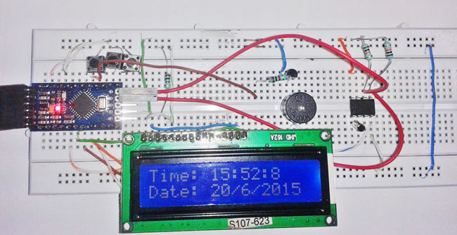
In this post I have explained how to make a simple digital clock using Arduino and a 16 x 2 LCD display. Learn how to create an Arduino-based alarm system with an I2C LCD display, RTC module, and button inputs for time and alarm settings. Arduino Digital Clock Using 7 Segment Display: In this post we are going to learn how to construct 16 digit - 7 segment display digital clock using Arduino. The clock will display date, time and temperature.

Digital Clock Circuit Using 16x2 LCD Display Circuit Diagram
With the circuit connections established, you have successfully set up the hardware for your Arduino digital clock with the DS1307 RTC module. The next step is to program the Arduino to control the clock's functionality and display the time and date on the LCD. Circuit Design Using PCB Software
