DIY adjustable voltage regulator Circuit Diagram
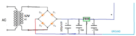
BlogDIY adjustable voltage regulator Circuit Diagram Guide to designing a simple 5V voltage regulator using the 7805 IC for stable power supply. Voltage regulators are essential components in electronic circuits, ensuring that the voltage supplied to devices remains constant despite fluctuations in input voltage or variations in load current.

A Zener diode is widely used as a voltage regulator to maintain a stable output voltage even when the input voltage fluctuates. Voltage regulation is essential for ensuring the proper functioning of electronic devices, making Zener diodes a crucial component in power supply circuits. Zener Diode Voltage Regulator Circuit Here we used a Zener as the reference and the transistor Q1 as a series regulator doing the hard work. R2 provides bias to turn Q1 on and supply a much smaller current through the Zener D2. If Vout is 5V, the base-emitter volt drop of 0.6V would be added to that, so D2 would need to be 5.6V (commonly available), and R2 would now have to supply the collector current/hfe of the transistor (say The LM317T variable voltage regulator also has built in current limiting and thermal shut down capabilities which makes it short-circuit proof and ideal for any low voltage or home made bench power supply. The output voltage of the LM317T is determined by ratio of the two feedback resistors R1 and R2 which form a potential divider network
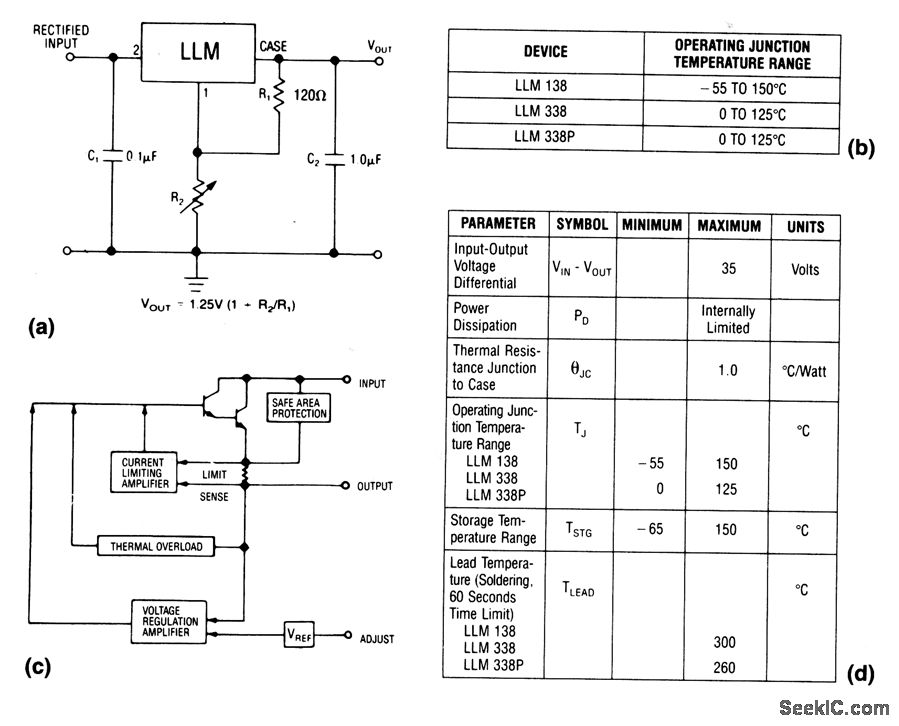
Variable Voltage Power Supply Using The LM317T Circuit Diagram
To understand its working, consider the circuit shown in the figure below. A voltage regulator circuit is installed between the supply voltage (input) and the electrical load (output). Due to some disturbances, the input voltage may either increase or decrease from its rated value. The voltage regulator acts accordingly to nullify the effect. A stable voltage supply is especially critical for devices that require precise and constant power, such as computers, smartphones, and other electronics. Without a reliable voltage regulator, the circuits could experience fluctuations that lead to errors, crashes, or even permanent damage. A step-up or boost regulator will generate a stable output voltage higher than the input voltage by using the input voltage to store energy in an inductor, released when this store is switched on. The voltage generated by the inductor adds to the energy already stored in a capacitor driven by the input voltage.
Voltage regulators are essential components in electrical systems, ensuring stable and consistent power delivery. At its core, a voltage regulator maintains a fixed output voltage, even when input voltage or load conditions fluctuate. Purpose: To deliver stable voltage to electrical devices. Function: Adjusts voltage to the desired level. Importance: Prevents damage from voltage spikes or drops.
