Compressor Audio Schematic Circuit Diagram
BlogCompressor Audio Schematic Circuit Diagram Support the channel.. through Patreon: https://www.patreon.com/moritzklein by buying my DIY kits: https://www.ericasynths.lv/shop/diy-kits-1/Simulati A DIY audio compressor circuit: Simple and effective. An audio compressor is an essential tool in the world of audio engineering. It helps to control the dynamic range of an audio signal, making it easier to manage and ensuring that the loudest and softest parts of a recording are both heard clearly. A compressor works by reducing the volume of The foundation for creating an audio compressor with BC547 transistors is provided by this circuit. In order to tune the circuit for certain audio qualities and performance requirements, extensive testing and changes will be required. How to Build: To build a Simple Audio Compressor Circuit, you need to follow the below mentioned steps:

Building DIY 1176 Compressor Some tips on building a do-it-yourself clone of the UREI 1176 FET Compressor , Rev. F The UREI 1176 Peak Limiter is a classic audio compressor designed by Bill Putnam, first built in 1967, making use of FETs and using them as a variable resistor to control the gain reduction in the circuit. You probably have the parts for this project lying around. It really works a treat! If you have any questions, then leave them in the comments and I'll do my The simplest audio clipper circuit configuration as shown above involves the use of a pair of diodes arranged back-to-back, limiting the signal's voltage swing to approximately 0.6 V, resulting in a form of hard clipping where the input signal waveform is essentially truncated or clipped sharply at the peak.
Simple Audio Compressor Circuit Circuit Diagram
About Press Copyright Contact us Creators Advertise Developers Terms Privacy Policy & Safety How YouTube works Test new features NFL Sunday Ticket Press Copyright
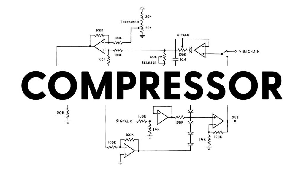
In this article, we'll explore the basics of a simple audio compressor circuit diagram and how it can help you create great sounding audio. A compressor circuit diagram typically consists of three key elements - an input, a compressor, and an output. The input takes in an audio signal, such as from a mic or instrument, and processes it through
Designing a simple audio compressor from scratch Circuit Diagram
A solenoid is a simple electromechanical device that converts electrical energy into linear or rotary mechanical motion. A . Automotive Relay Guide Browse through our collection of free DIY audio compressor circuits, projects, and schematics. Plus, find helpful diagrams, step-by-step instructions, and more.
