Circuit With Logic Gates Circuit Diagram
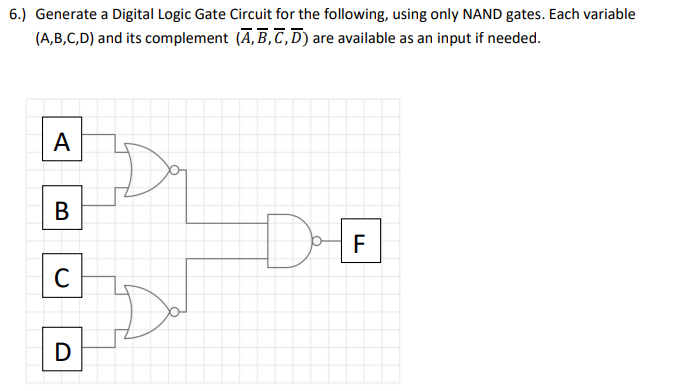
BlogCircuit With Logic Gates Circuit Diagram 4.1.1. Logic Gates with Multiple Inputs¶. Assume we design a digital circuit and need a NAND gate with 3 inputs. We may assemble the 3-input NAND gate using 2-input NAND gates and an inverter as building blocks, see Figure 4.1.Using Boolean algebra, it is straightforward to show that this circuit implements the logic function \(Y = \overline{A\,B\,C}.\) Simple Logic Gates and Circuits: Logic gates are some of the basic building blocks of digital logic circuitry. In this Instructable we will talk about a few of the simplest of these devices, and see some of the fun things you can do with them. Here we outline two simple ways to design a logic circuit that results in the exact truth table we

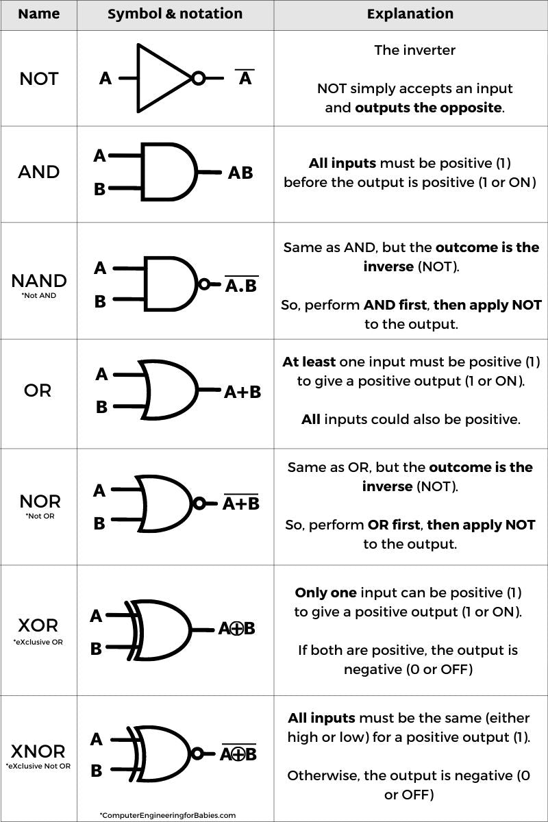
Combinational circuits are built of five basic logic gates: AND gate - output is 1 if BOTH inputs are 1; Digital logic circuits are usually represented using these six symbols; inputs are on the left and outputs are to the right. When a computer's "speed" is cited, this is the value in question. It is possible to design "asynchronous
SparkFun Learn Circuit Diagram
Logic gates are the basic building blocks of digital electronics. These are the components that we use for "doing stuff" with the 1s and 0s. You can combine them to create other building blocks like latches, flip-flops, adders, shift registers, and more. The basic logic gates are AND, NAND, OR, NOR, XOR, XNOR, and NOT.

Introduction to Digital Logic Design CSE 140: Components and Design Techniques for Digital Systems . Winter 2016 . three basic 'logic' operations: 1. Intersection: AND (2- input); Operator: . 2. Union: OR (2-input); Operator: + circuit it represents by cascading gates (and vice versa) Next class • Designing Combinational circuits
Logic Gates: Understand The Basics of Digital Electronics Circuit Diagram
It involves using logic gates and combinational and sequential circuits to create complex digital systems that can perform a variety of tasks. What are the prerequisites for learning digital electronics and logic design? A basic understanding of electrical circuits and fundamental concepts in electronics is recommended. Familiarity with binary Here are some key digital devices in which logic gates are utilized to design their circuits. Computers; Microprocessors; In the Digital System, logic gates are the basic building blocks. Â In these logic gates, we can find the gates having more than one input, but will have only one output. The connection between the input and the output

Most digital logic gates and digital logic systems use "Positive logic", in which a logic level "0" or "LOW" is represented by a zero voltage, 0v or ground and a logic level "1" or "HIGH" is represented by a higher voltage such as +5 volts, with the switching from one voltage level to the other, from either a logic level "0" to a "1" or a "1" to a "0" being The 7 basic digital logic gates are AND, OR, NOT, NAND, NOR, XOR, and XNOR. What are Universal Gates? Universal gates are specific types of logic gates that can be used to implement any other type of logic gate. In other words, a single universal gate can be used to perform all the basic logic operations required for digital circuit design.