amp circuit that would add an integrated input with Circuit Diagram
Blogamp circuit that would add an integrated input with Circuit Diagram The following capacitance meter circuit includes 4 ranges using full scale values of 5nF, 50nF, 500nF and 5µF, which allows it to be employed for testing a large number of capacitors. The miller integrator is built around a standard operational amplifier type that is designed using IC2. The fundamental working of the circuit is to present
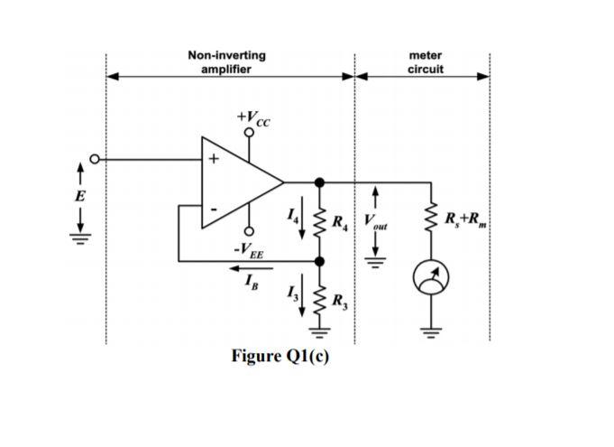
Op amp IC1 is attached like a comparator, with its (+) input pin attached to R8, which fixes the reference voltage level. Prior to supplying power to the capacitance meter circuit, use a fine screwdriver to adjust the meter M1 needle precisely to the zero level. Position an accurately known capacitor around 0.5 and 1.0 µF at +/-5%. This

Capacitance Meter With Arduino and 741 Op Circuit Diagram
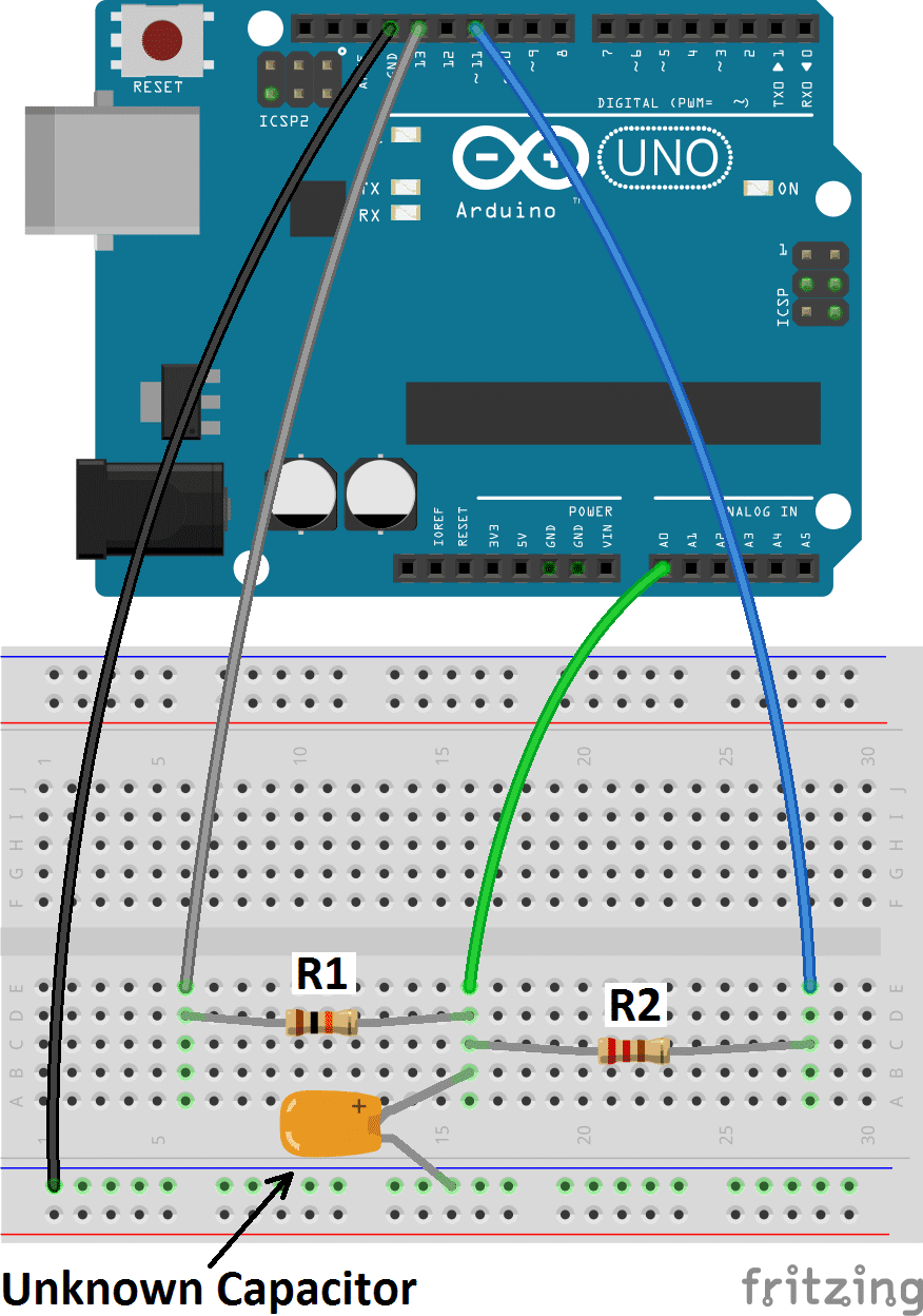
Good for lighting LED's, driving other circuits - useless for reading sensors. Additionally the pins can be HIGH (+5 volts), to charge the capacitor; or LOW (ground) to discharge the capacitor. Algorithm for capacitance meter sketch. Set discharge pin to INPUT (so it can't discharge the capacitor) Record the start time with millis()
The capacitor is then discharged into the meter circuit. The meter measures the current being drawn through the 47 ohm resistor. The 555 repeats the process several times a second, so that the meter needle remains steady. The deflection on the meter is directly proportional to the value of the unknown capacitor. Op amp IC1 is attached like a comparator, with its (+) input pin attached to R8, which fixes the reference voltage level. Prior to supplying power to the capacitance meter circuit, use a fine screwdriver to adjust the meter M1 needle precisely to the zero level. Position an accurately known capacitor around 0.5 and 1.0 µF at +/-5%. This
Capacitance Meter (with Pictures) Circuit Diagram
As I mention earlier the board is designed to operate at 5V power so it has an 5V regulator. A 2.1mm core power connector is used to provide power to the circuit. Connect and solder it to the PCB. You can use 7-16 V DC adapter to power the meter using this DC connector. b) R1.Cf is not >> input period. Then you need to allow for R1 and know the frequency if you are calculating the gain. If you are simply making a capacitance meter, and you calibrate the scale with a known capacitor, and keep the frequency constant, then you can ignore their actual values. The principle of operation of this meter is based on the determination of the time T that it takes to charge an unknown capacitor C through a known resistor R from 0V to a voltage reference level (Vref) which is determined by a simple voltage divider formed by R1 and R2.. I chose R1 = R2 so that Vref = VCC / 2 making the calculations easier.. VCC for the comparator circuit is provided by the