am radio circuit Page 5 RF Circuits Nextgr Circuit Diagram
Blogam radio circuit Page 5 RF Circuits Nextgr Circuit Diagram Construction of AM Radio Receiver Circuit starts with local tuning Setup, AM Radio Ferrite coil and Variable Gang Capacitor makes the Local Oscillator and Resonates with the tuned channel and Removes the Carrier Signal and then Germanium diode (0.3V cut in voltage) will allow the positeve side that is upper side band and removes (Rectification
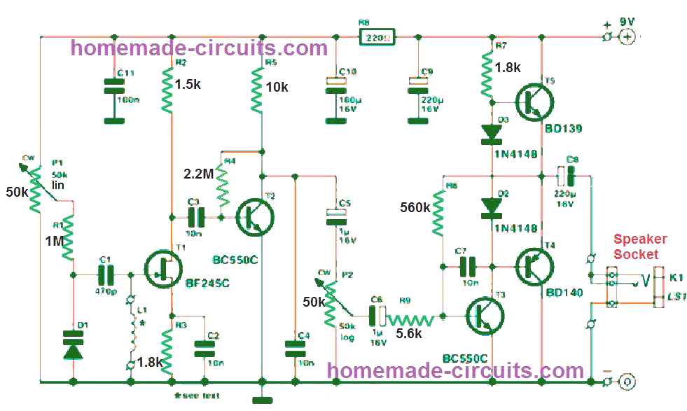
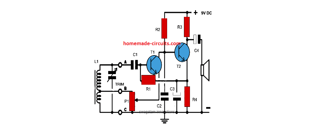
Circuit Operation. As can be seen in the given circuit diagram, the design is as simple as it can be, just a couple of general purpose transistors and a few other passive components for configuring what looks like a nice little AM radio receiver unit. The first AM radio has no amplifier and only relies on resonance to create sound. The second AM receiver has a transistor amplifier, LM386 Amplified AM Radio. The circuit below is basically the same crystal radio circuit as above, but the speaker has been replaced with an LM386 audio amplifier. This will allow the radio to work without an Figure 7: Receiver Circuit Figure 7 shows the circuit you will build for your radio receiver. This circuit consists of four basic sections: a "tank circuit", a diode, a low pass filter, and a non-inverting amplifier. The inductor-capacitor parallel combination is commonly called a tank circuit. The tank circuit is
Understanding and Building an AM Receiver Circuit: A Comprehensive Guide Circuit Diagram
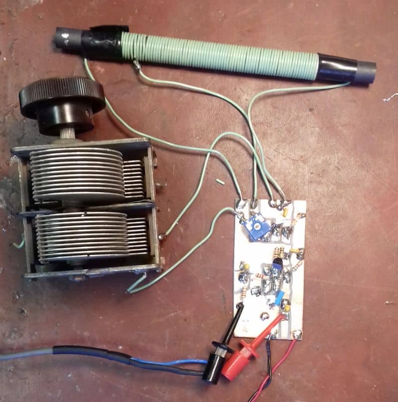
It's time to create the magic circuit that will tune the beautiful AM radio waves out there, almost for free :) -Because we are making a tank circuit (in parallel) is mandatory to solder the coil in parallel with the trimmer capacitor, in other words, one lead to the coil to one lead of the variable capacitor.
Block Diagram of an AM Receiver Circuit. An AM (Amplitude Modulation) receiver circuit is used to receive and decode amplitude modulated signals from radio stations. The receiver circuit consists of several blocks that work together to perform the necessary functions for receiving and demodulating the AM signal.
¡BUILD AN AM RADIO RECEIVER! Circuit Diagram
The tuner typically consists of a variable capacitor and an inductor, which together form a resonant circuit that can be tuned to different frequencies. When the tuner is properly adjusted, it allows the radio to receive the desired AM radio signals while rejecting unwanted signals from other stations. The AM radio receiver schematic also This is used when there are 2 different voltages in a circuit. In this radio, there is only one voltage is used. If the jumper wires are connected such that one is in the left side of a row and one is in the right side of a row, the radio will not work. To create a simple AM radio, start by coiling up 15-50 feet of 20-22 gauge insulated

I am making an AM radio with the specifications of: Part 1. Design a circuit with an antenna for tuning your receiver to a signal of a specific carrier radio frequency so that you can select a certain radio station. The frequency range is from 526 kHz and 1706 kHz at 10 kHz intervals.